WHAT IS PERSISTENCE OF VISION?
Persistence of vision refers to the optical illusion that occurs when visual perception of an object does not cease for some time after the rays of light proceeding from it have ceased to enter the eye. The illusion has also been described as "retinal persistence", "persistence of impressions", simply "persistence" and other variations.
OUR DESIGN
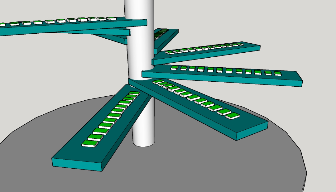
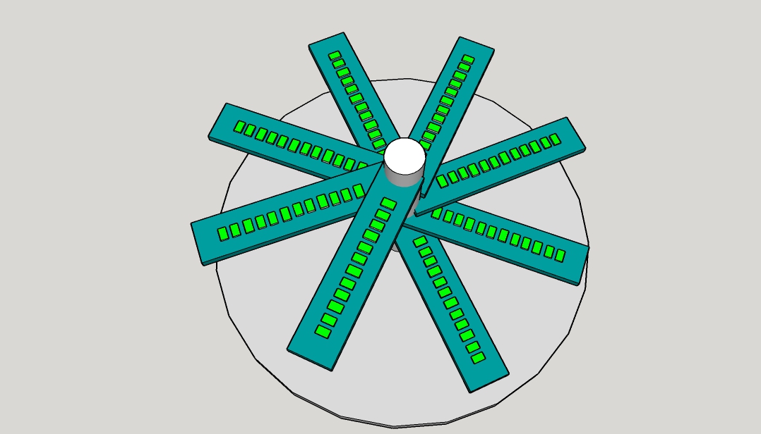
We designed an LED display that applies the idea of persistence of vision to give the user the effect of seeing 3D images. Persistence of vision is applied to our display by having LEDs rotate around a single central axis, creating the illusion of a full volumetric display.
While designing our 3D LED display, the goal was to create a higher resolution (pixel density) than previous projects that have used this approach. Another important challenge that we addressed is having a high number of colors that can be displayed. Other designs that we have seen only turn the LEDs fully on or fully off. That means unicolor designs only have one bit of color, while designs that use RGB only get 3 bits of color (8 colors). We speculate that these limits were imposed simply because driving a 3D rotating display is much harder than a single layer display.
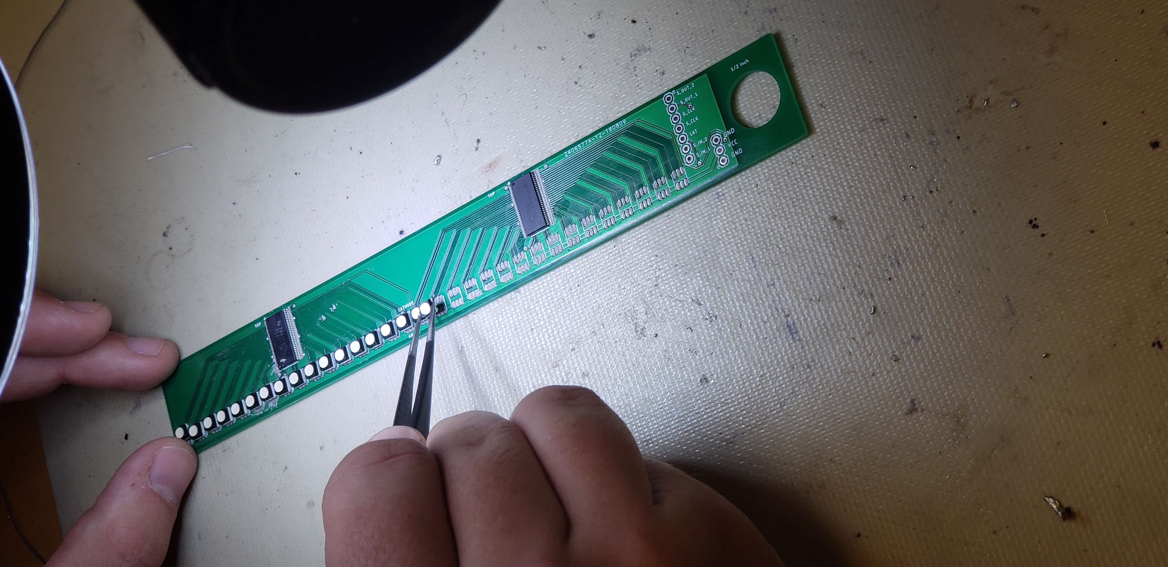
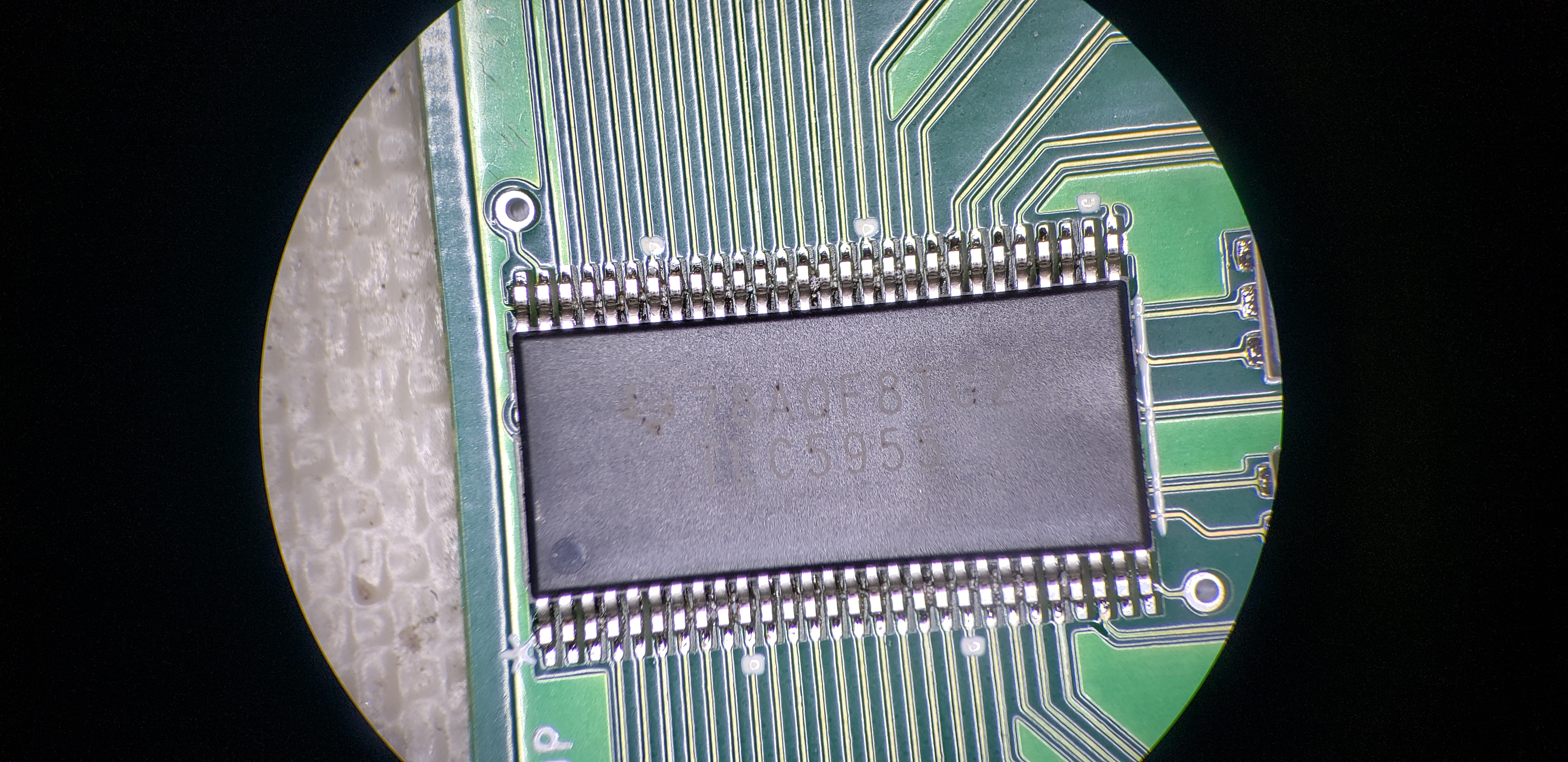
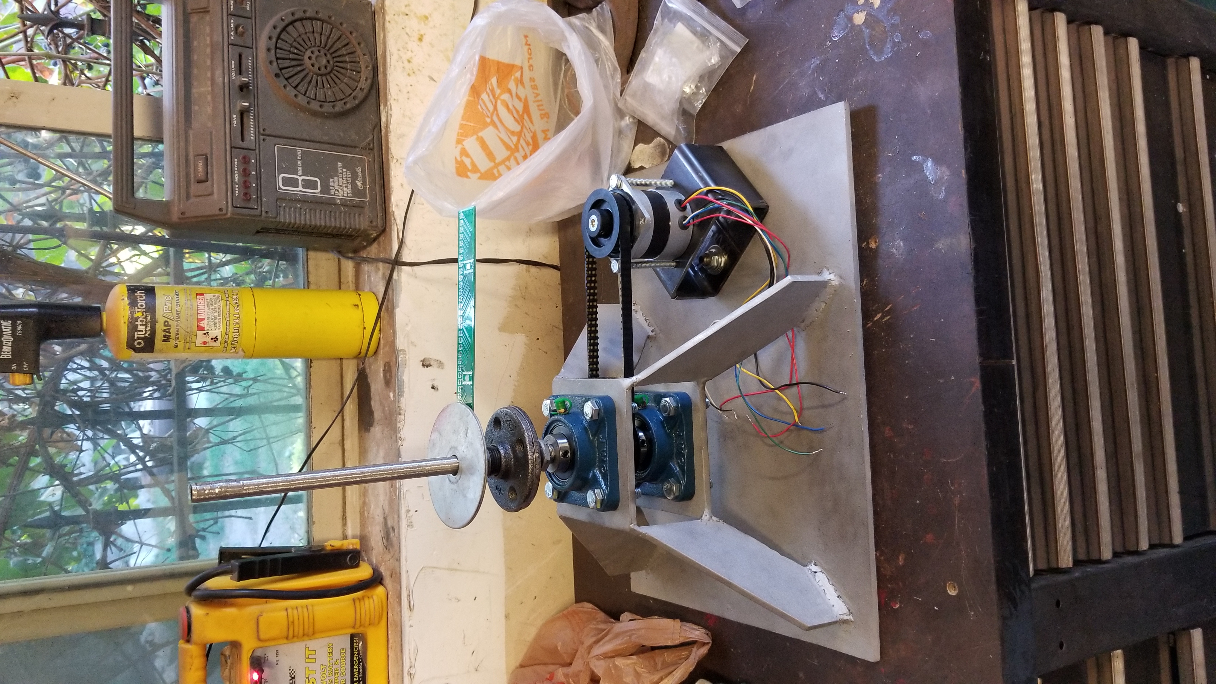
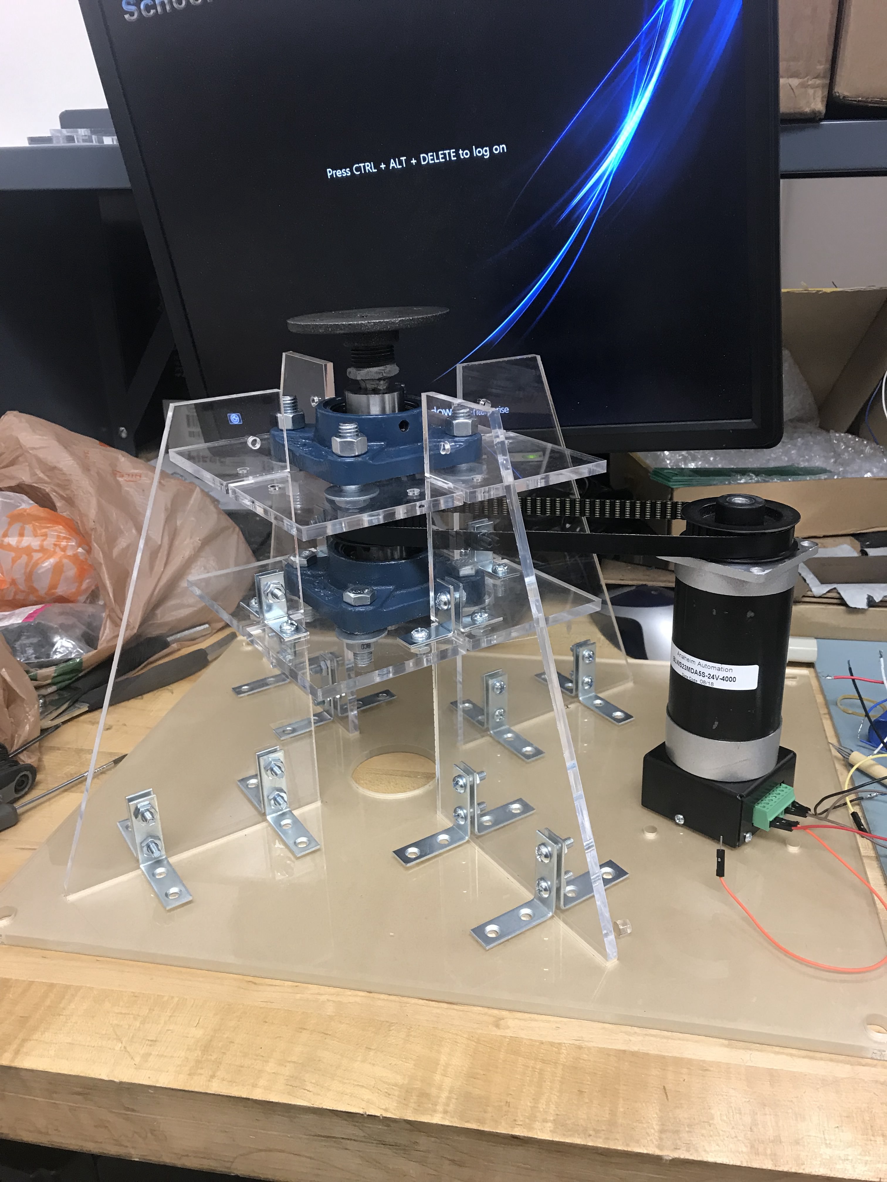
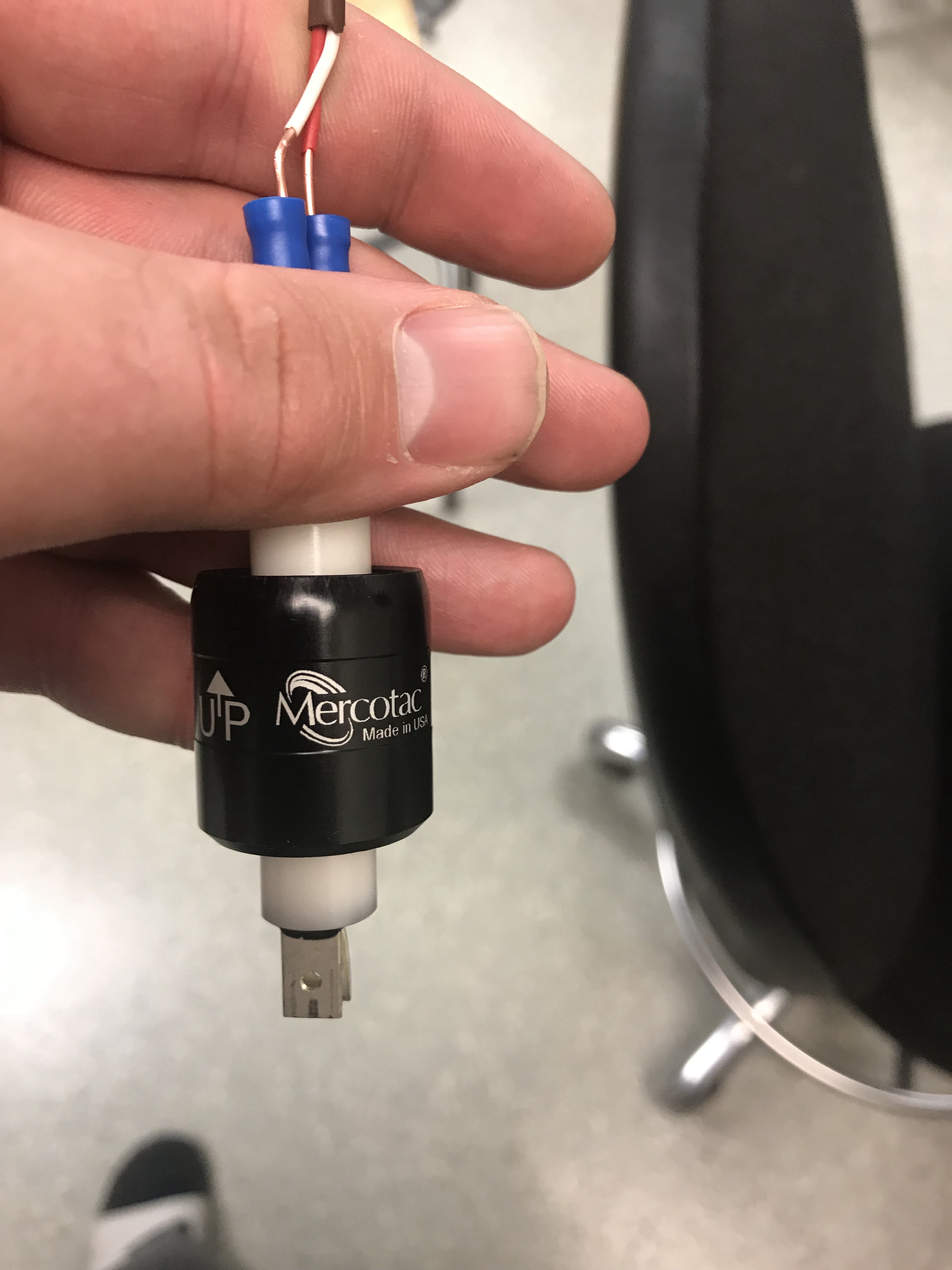
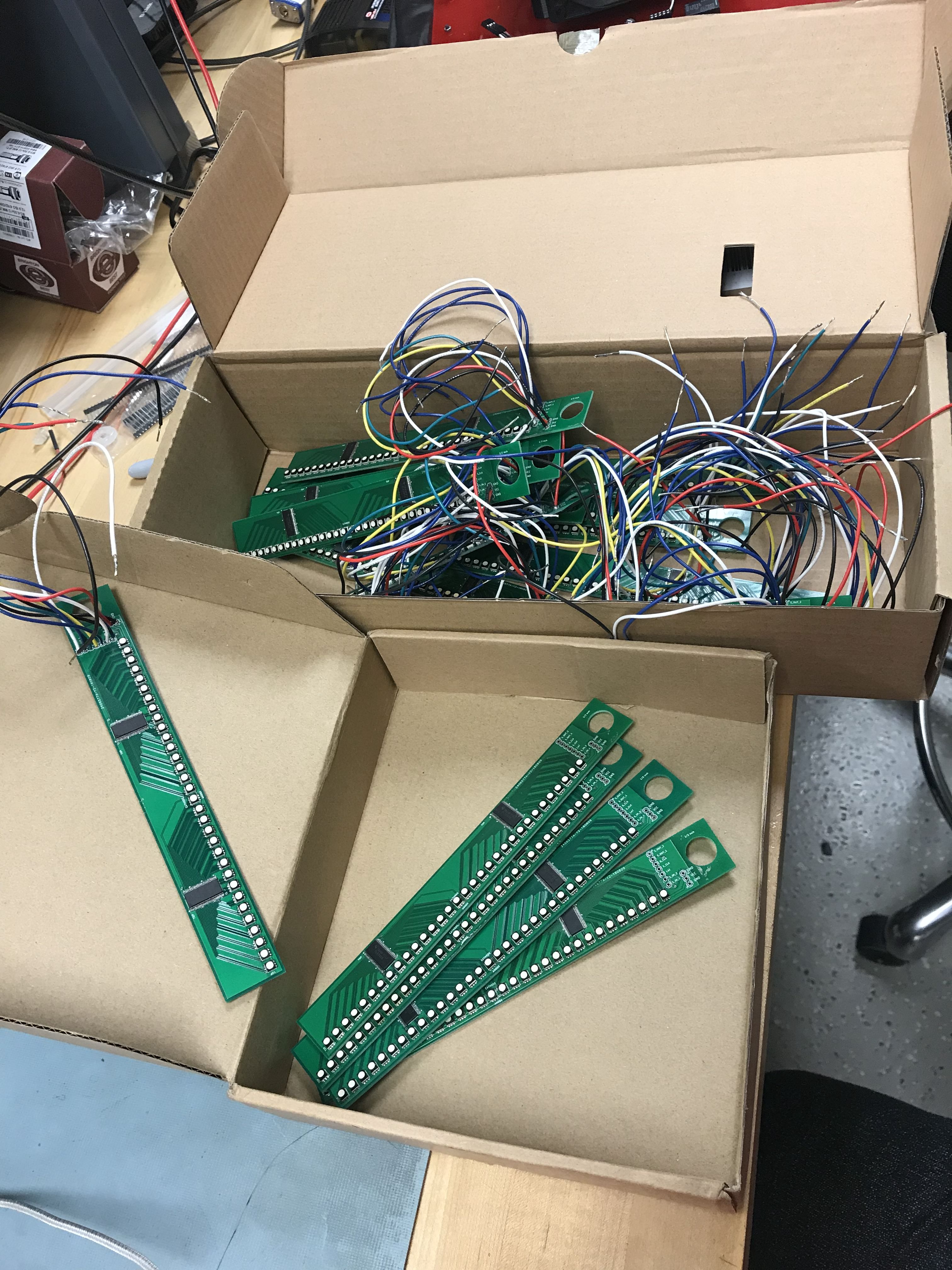
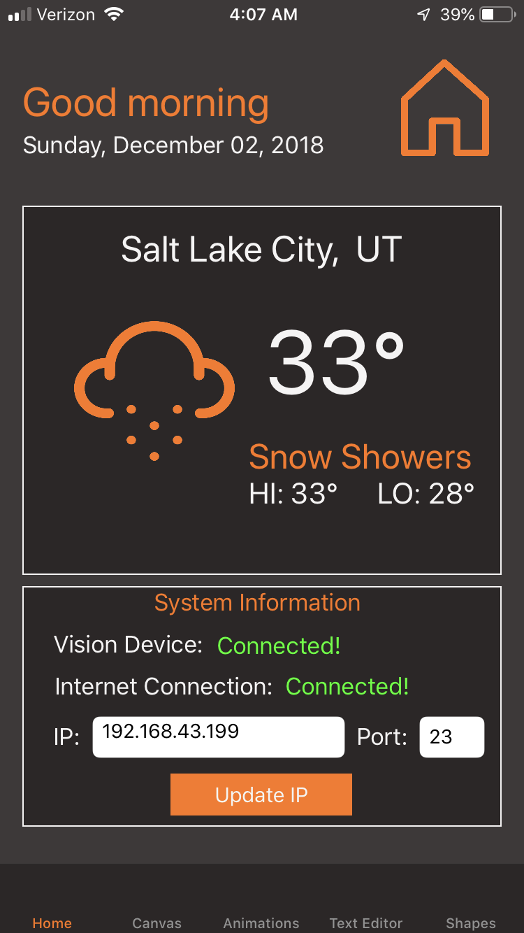
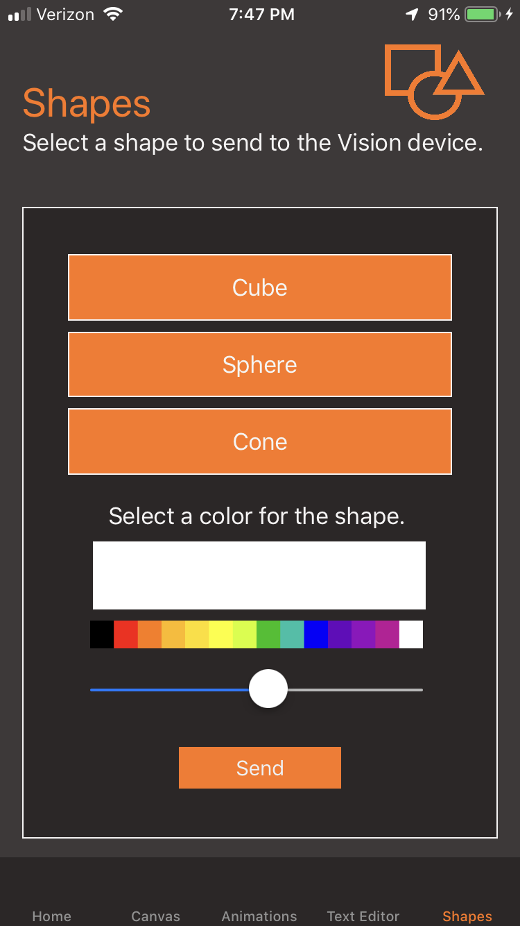
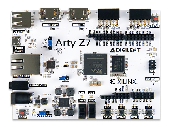
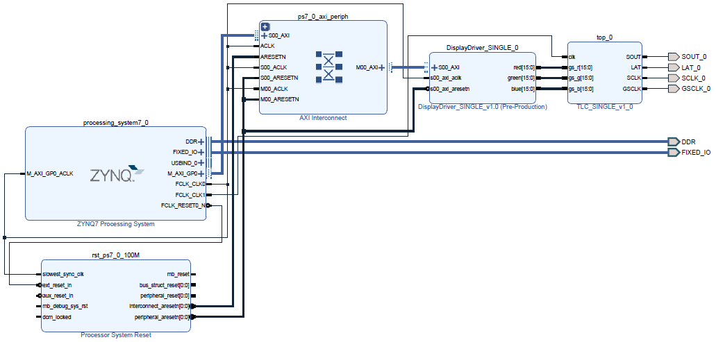
For our project, PWM was used for each LED in order to get a wider range of colors. Our project is capable of displaying 7 vertical pixels, 32 radial pixels, and 360 sections around the circumference (akin to a pie chart with 360 equal sections, where the radius is 7 units and a depth of 32). The general design of our project involves having most of our control logic (main board) located on the rotating display itself. This is namely because finding an inexpensive slip ring that fits our needs was rather difficult. This means that we had to be able to wirelessly transmit the data to the controller through wifi using an ESP8266 chip by way of an iOS mobile application. Up through the central axis is a rod that allows us to attach 7 individual PCBs (each containing 32 LEDs). Each PCB has two LED drivers on it, which takes in serial data and translates that into the appropriate brightness for each LED. The assembly also included a sensor in order to synchronize the rotation of the display with the controller
The control board takes in the appropriate scene data and converts it into the required pixel data. This required implementing a graphics rendering algorithm in order to work with polar coordinates. When the assembly is at the appropriate rotation, the control board will send out the corresponding serial pixel data to each arm of the display. Once a full rotation is made, the next frame is processed/displayed.